 |
Eureka Project E!5820 Ś 2DLMP2-D Laser System for Material Processing
| Overview |
Phase I |
Phase II |
Phase III |
Phase IV |
Contact |
Phase III ¢ Integration of the laser system on the machine; testing of the 2-D laser system equipment; final version of the execution specifications for manufacturing; reports of the economical efects obtained
Deadline: 30.03.2014
Task III.1 - Integration of the laser system on the machine and tests on the laser system equipment
Task III.2 - Final versions of execution and implementation documentation
- Task III.2.0 - Final version of the documentation of the drive
- Task III.2.1 - Final version of the documentation of the linear motor
 Results of Phase III: Results of Phase III:
- Technical specification for linear motor development
- Documentation of linear motor production
- Technical specification for linear motor drive development
- Documentation of linear motor drive production
- Specification for laser system equipment development
- Documentation of laser system equipment production
Consorţiul din România a realizat :
- An experimental model of the equipment for the laser system
- An experimental model and prototype of the motor and drive
- The production documentation for all products developed by the Romanian partners
- One patent application submitted
- Integration of all components into the final product (together with CIVAN)
The subassemblies developed by Technosoft and ICPE are based on the following components:
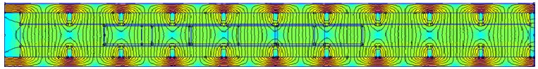
- Electric motors: A system of three 3-phased linear motors (for Axes X1, X2 and Y of the 2D stand), as well as a rotating permanent magnet brushless synchronous motor (for Axis Z); all motors have been developed by ICPE. The linear motors have a total stroke of 500 mm in each moving direction, and they are equipped with sin-cos linear encoders of a 1-Ąm accuracy. The linear motors have been designed to ensure the imposed parameters (current, voltage, lineary force) and their performances are very good in terms of dynamics, force uniformity (extremely low reluctant forces) and low static friction. The linear motors have an ironless winding which represents the active par that moves with the load. The passive part is composed of two identical metal plates facing each other, having permanent magnets with alternate polarities fixed on their inner sides. There is no mechanical contact between the two parts. The motor is supplied with 3-phased alternating voltages.
As there is no iron in the active part, there are no iron losses either, no parasitic hanging forces between magnets and iron teeth; the magnetic attraction forces between the active and passive parts are null, unlike with other permanent magnets motors. This type of motor is mainly used in applications that require high dynamics, due to the small weight of the active part.
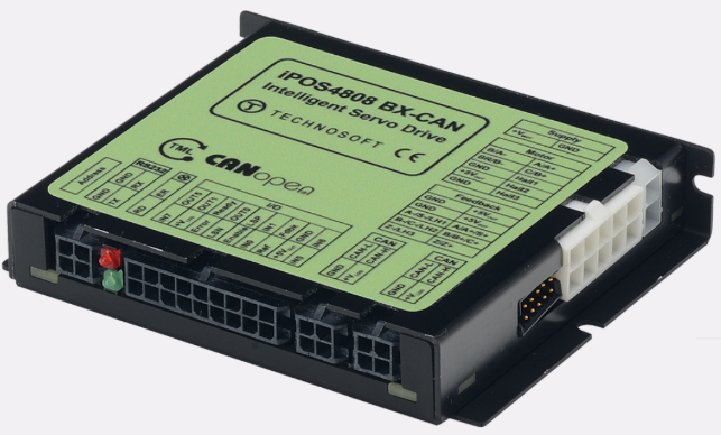 Electric drives: Four digital drive systems have been developed by Technosoft: model iPOS4808-BX-CAN, with a rated supply voltage of 48 V, a 3-phased output static convertor, 8 A nominal current and 20 A peak current. The drives are based on TechnosoftÆs MotionChipÖ technology and they enable the control of 3-phased linear or rotating motors equipped with a position controller of an incremental or sin-cos encoder type. Torque, speed or position control is available. The drives are high-level programmable in TML language and they can communicate through a CAN bus. The motion commands and axis synchronization will be realised by Civan within the specific activities of final integration with the laser component. Electric drives: Four digital drive systems have been developed by Technosoft: model iPOS4808-BX-CAN, with a rated supply voltage of 48 V, a 3-phased output static convertor, 8 A nominal current and 20 A peak current. The drives are based on TechnosoftÆs MotionChipÖ technology and they enable the control of 3-phased linear or rotating motors equipped with a position controller of an incremental or sin-cos encoder type. Torque, speed or position control is available. The drives are high-level programmable in TML language and they can communicate through a CAN bus. The motion commands and axis synchronization will be realised by Civan within the specific activities of final integration with the laser component.
The iPOS4808-BX-CAN intelligent drive can operate at a supply voltage of up to 48 V. It can generate 8 A currents (20 A short-duration peak currents). Measuring the position information from the encoder enables the user to measure the position with an accuracy depending on the transducer used (the system has been provided with 1-Ąm accuracy on axes X1, X2 and Y).
The drive can communicate with other axes through the CAN interface, making it possible to implement the motion coordination in multi-axis, electronic gearing or camming systems, etc. Equipped with 8 digital inputs, 5 digital outputs and 2 analog inputs, the drive can be programmed in the TML motion language, which enables implementing complex motion applications and PLC functionalities, or the drive being able to receive online TML commands on the RS-232 channel or on the CAN bus.
For the control of Axis Z, the equipment includes a laser sensor with an accuracy of 50 Ąm that operates within a 10 cm range. The signal provided by this sensor has been used to permanently control the distance from Axis Z to the surface of the material to be cut by the laser mounted on Axis Z.
- A mechanical system for the mounting of the 3-axis assembly.
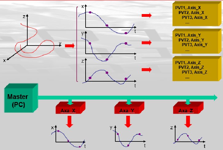 As the drives on each axis are provided with advanced reference generators that enable the local computation of trajectiories on each axis through higher-order interpolation type methods, the tasks of the master and of the communication channel between master and axes are significantly reduced. This has enabled a simpler computation of the trajectory that has to be generated at master level (type PC, PLC, etc.) and a simpler control of the system axes by using advanced PVT commands, which will then take over, at each axis level, the task of interpolation computing (e.g., third order polynomial) through specific PVT commands. As the drives on each axis are provided with advanced reference generators that enable the local computation of trajectiories on each axis through higher-order interpolation type methods, the tasks of the master and of the communication channel between master and axes are significantly reduced. This has enabled a simpler computation of the trajectory that has to be generated at master level (type PC, PLC, etc.) and a simpler control of the system axes by using advanced PVT commands, which will then take over, at each axis level, the task of interpolation computing (e.g., third order polynomial) through specific PVT commands.
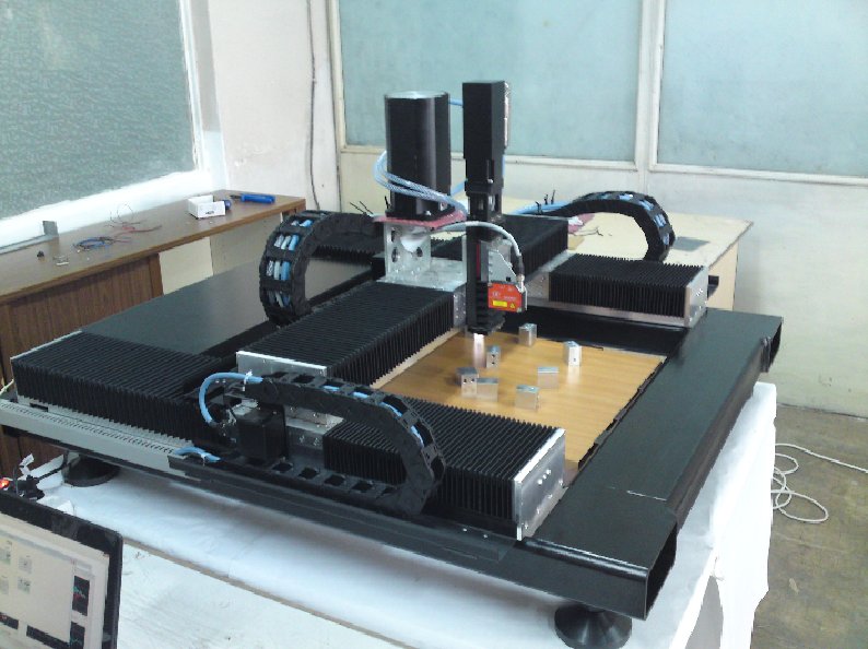
The results of the tests performed on the overall experimental structure have validated the project, by confirming that the design specifications have been met. The equipment testing consisted of running all motor and drive tests on axes X1, X2, Y and Z of the machine, as well as motion tests on each axis. The tests have been performed using the Technosoft EasyMotion Studio application, which allowed for an optimal axis configuration and recording of results. Some applications have been implemented in the TML motion language, which enabled trapezoidal profile motions and the highlighting of dynamical and positioning accuracy performances. Maximum 5-Ąm accuracies have been obtained, which places the results within the specification limits required by the project (10 Ąm). The maximum speed recorded on axes X or Y were of over 1 m/s, as required by the design specification.The figures below present examples of different individual moves performed on axes X1, X2 and Z of the machine.
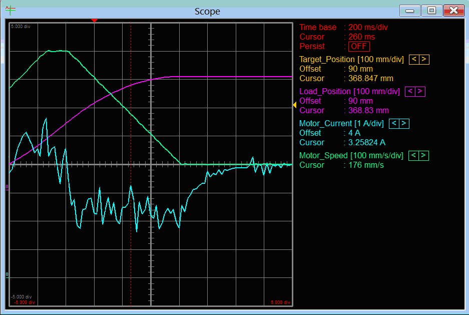
Oscilloscope reading during move |
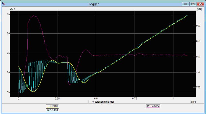
Motion logger reading on axis Z |
The experimental prototype thus achieved confirms that the performances imposed by design specifications have been reached. The new products developed by the Romanian partners for the project ¢ both the permanent magnets synchronous linear motors model CLM 32-57-56, and the intelligent drives model iPOS4808 BX-CAN ¢ represent top performance products that will be able to be manufactured and marketed, both as the 2D laser system designed, and as components of other advanced OEM equipments for different domains of the high-performance industrial automation range.
Testing equipment with linear motors and drives (Axes X1, X2, Y) and with rotating motors and drives (Axis Z)
|