The
external reference mode can be configured through the “External reference” group box in the “Drive Setup” dialogue, function on the selected “Control mode”.
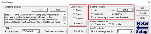
Pressing the “Setup” button in the “External reference” group box, will
open the “External Reference Setup” window, which allows defining the
external reference type and setting its parameters.
The
external reference source can be an analogue signal (0V…5V or +/-10V, depending on the drive type and settings)
or a digital signal (“Pulse & Direction” or “Secondary
Encoder”).
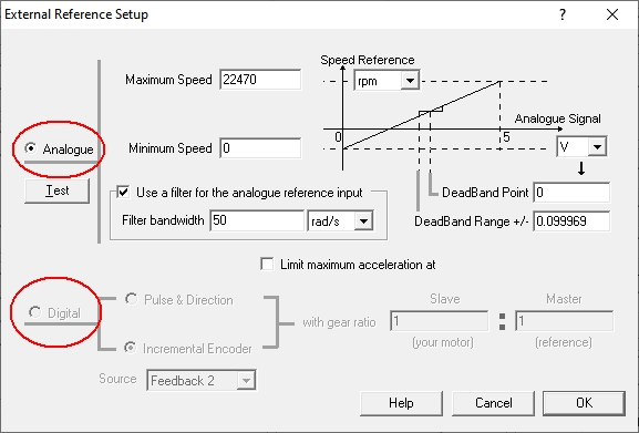
Analogue Reference
When the “Analogue”
reference type is selected, the minimum and the maximum command that corresponds to
the min. and max. voltage reference values (there is a linear dependence
between the 2 parameters) must be configured.
A test can
also be done, to see the evolution of the imposed reference based on the analogue
voltage signal.
F
Since the low voltage analogue signals can be easily
affected by the electromagnetic noises and the analogue to digital conversion
itself is subjected to some jitter, the drive has some means to compensate them:
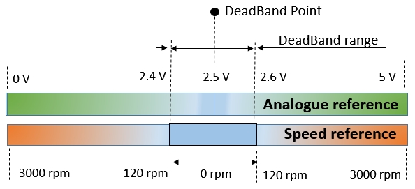
a first order filter, to make the reference smoother, a “DeadBand
Point” and a “DeadBand Range” option, to create a voltage
interval where the reference will be kept constant to prevent the motor
movement / vibration when the analogue signal is stationary.
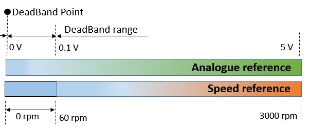
Example 1
Analogue reference: 0 … 5 V;
Speed reference: 0 rpm … 3000 rpm;
Dead bad point: 0 V;
Dead band range: 0.1 V.
Example 2
Analogue reference: 0 … 5 V;
Speed reference: -3000 rpm … 3000 rpm;
Dead band point: 2.5 V;
Dead band range: 0.1 V.
Remark: The reference from an analog input can have values from 0 IU to 65535 IU, or
from -32768 IU to +32767 IU. Depending on the feedback sensor resolution,
this range can be insufficient. In this case the analog reference reading, filtering, scaling and conversion to a position or speed command should be implemented as a TML application program. The following article describes this case in details: Analog reference scaling to a 32-bit position or speed reference [gb/cm]
Digital external reference
The
digital external reference can be “Pulse
and Direction” signals or the output
of a master encoder.
The
wizard allows the user to set where’s the reference coming from (to “Feedback
#1” or “Feedback #2”) and what is the ratio between the position signal and the
output command. Setting a 1:10 ratio, for example, means that the motor will
perform 1 IU on every 10 pulses, received from the master.
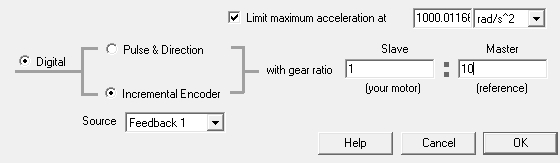
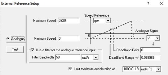
To
prevent the shocks that can occur due to a rapid change of the reference
signal, the “External Reference Setup
External Reference Setup” window allows setting an acceleration
limit too.
Keep
in mind that exceeding the acceleration limit will result in pulses loss.
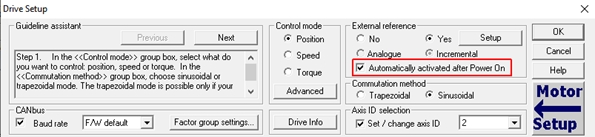
Activating the external reference
For simple applications, where the drive should only work in the external
reference mode, there’s the “Automatically
activated after Power On” option that will activate the mode
(automatically, as the name suggests) after the drive is powered ON.
If
a TML application program is stored on the drive and the AUTORUN mode is
active, the “Automatically activated
after Power On” option will have no effect. The drive will execute the program stored
in its memory. In this case, the external reference mode can be activate in the
TML program, through the “Motion –
External” wizard in the “Motion”
branch.
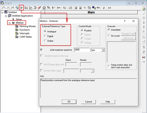
The
“Online” option in the “Motion – External” wizard allows to
send the position, speed, torque or voltage reference via the communication
channel, by writing the reference value into a specific variable:
·
Position reference: EREFP
·
Speed reference: EREFS
·
Torque reference: EREFT
·
Voltage reference: EREFV
The values
written in the above variables will be interpreted as IU (drive internal
units).
The
drive internal units are detailed in the EasyMotion Studio help topics (Help | Help Topics | Application Programming
| Internal Units and Scaling Factors).
 Categories