The Tune & Test dialogue allows to automatically tune the active controllers, test the results and adjust the controllers parameters.The automatic tuning interface can be opened by pressing any of the Tune and Test buttons in the Drive Setup dialog.
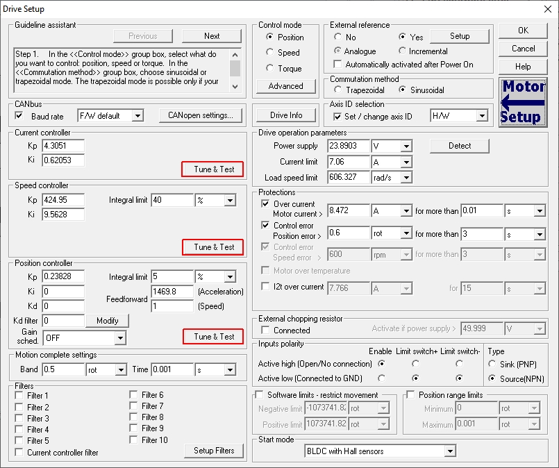
When the Tune & Test button is pressed for the first time or when the current limit or the protections values were manually changed, the software proposes a set of value computed based on the motor nominal and peak current values, from the Motor Setup dialogue.
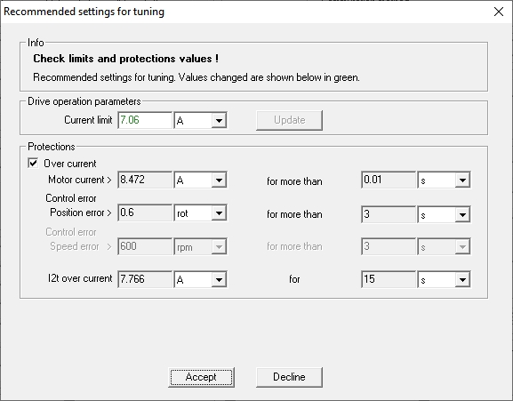
The proposed values can be accepted (if they met the application requirements) or declined.
Accepting this values will automatically modify the value in the Drive Setup dialogue too.
If the Decline button will be pressed, the Tune & Test interface will use the values in the Drive Setup dialogue.
Once current limit and the protections are set, the Tune & Test dialogue opens with the Automatic Tuning tab selected.
The Automatic Tuning tab can be used to automatically identify the system parameters and find the active controllers parameters.
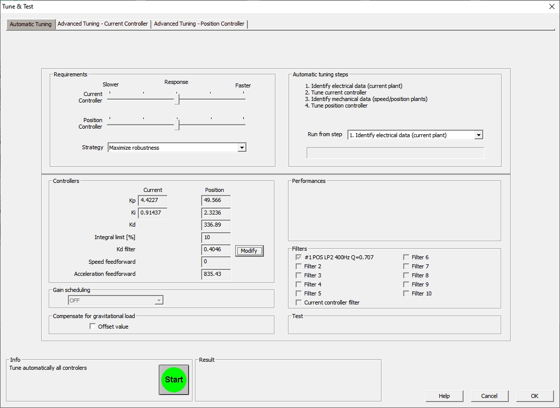
The Requirements group box allows to customize the automatic tuning procedure. Via the Response sliders, a trade-off between a Faster (higher bandwidth response) and a Slower (more robust response) can be choose.
The Strategy drop list allows to chose different tuning strategies, like for example: Maximize stiffness or Minimize settling time.
The Automatic tuning steps group box displays the steps to perform.
Using the Run from step drop list, the tuning procedure may be set to step over some tuning steps previously performed.
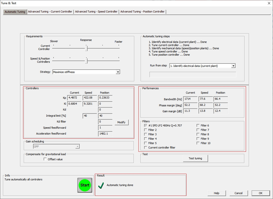
The Controllers and Performances group boxes present the tuning results.
The Controllers group box, displays the new values for Current, Speed and Position controllers.
The Performances group box shows the estimated performances for each control loop: closed-loop bandwidth and open-loop phase and gain margins.
In some cases, the automatic tuning may include a low pass filter. When this happens, the Filters group box shows the filter type and settings: SPD – applied on speed controller output, POS – applied on position controller output; LP1 – 1st order, LP2 – 2nd order, cut-off frequency in Hz and quality factor Q (only for LP2).
The Gain scheduling drop list shows if the automatic tuning has been done with or without Gain scheduling. When tuning is done with gain scheduling, the drop list shows its type.
If the application has a vertical axis, the Compensate for gravitational load option allows to add a constant offset to the current/torque command.
The automatic tuning procedure can be started by clicking on the Start button. The tuning procedure status and progress will be displayed in the Automatic Tuning Steps box.
When the tuning procedure will end, a message will be displayed in the Result box. The controllers parameters and other details related tot the tuning results will be displayed in the Controllers and Performances group boxes.
The controller behavior can be tested / modified by selecting the Advanced Tuning tab for the desired controller. Below is an example for the Current Controller - Position configuration.
The current controller is a PI (proportional - integral) type controller. The proportional part (Kp) is responsible for the answering time, while he integral part (Ki) parameter eliminates the stay state error.
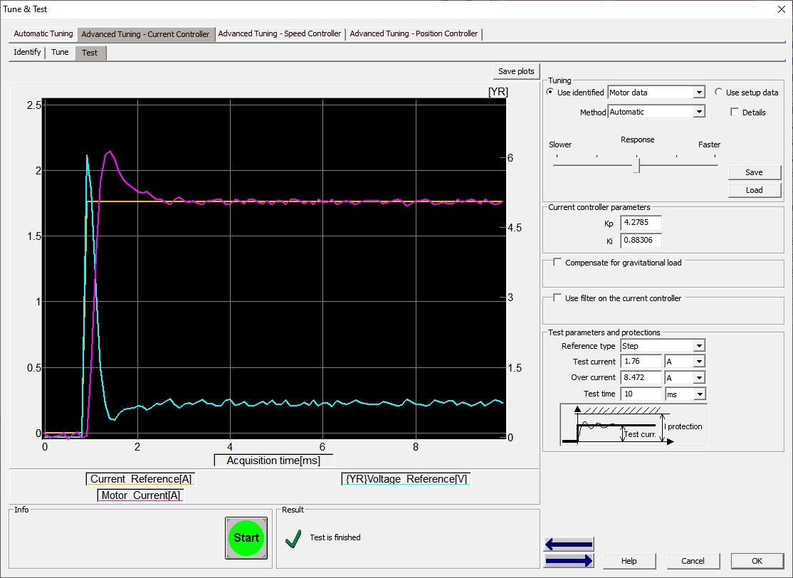
The Test tab allows to impose a step reference (Test parameters and protections group box) and see the controller response (when clinking on the Start button).
If the response doesn't meet the application requirements, a trail and error process can be adopted, until the current controller will answer as required.
The controller parameters can be changed using the Kp and Ki fields in the Current controller parameters group box.
The position controller is PID type and can be accessed by selecting the Advanced Tuning - Position Controller tab in the Tune & Test dialogue.
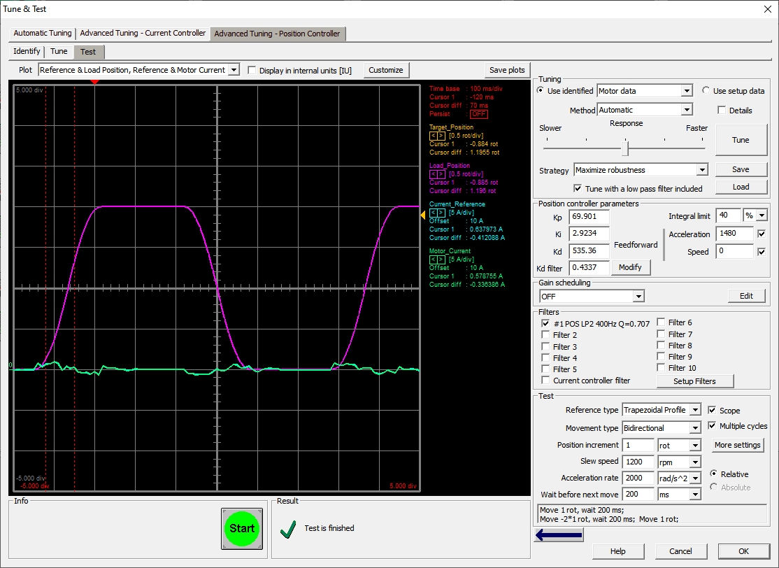
The Test tab allows to chose the reference type (Test parameters and protections group box) and set its parameters.
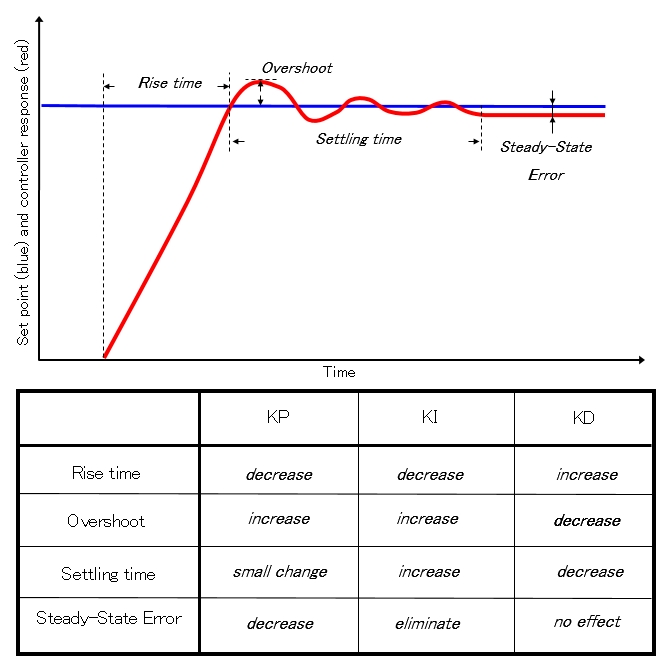
The Position controller parameters group box allows to adjust the controllers parameters. Below is an overview of their effect.
The parameters effect on the imposed profile will start to be plotted after clinking on the Start button.
As a difference from the current controller, in case of the position controller the parameters can be modified on the fly, without stopping and restarting the test each time a parameter is changed. The only condition is to click in another box, after a parameter is changed.
Once the controllers answer met the requirements, the parameters can be saved by exiting the Tune & Test dialogue with OK.
The new parameters can be transferred to the drive using the setup Download to the Drive/Motor option in the Setup dialogue and will became active after the drive reset.
 Categories