The EtherCAT synchronization procedure assures a good timing between the drive internal loops and the EtherCAT communication cycles. This functionality is detailed in chapter “3.2 EtherCAT® Synchronization” from the “CoE Programming Manual”.
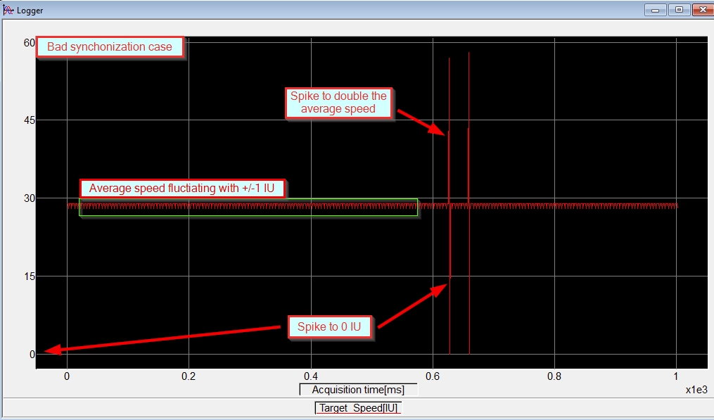
If there’s a synchronization issues, it can be simply detected by checking the Target_Speed or TSPD variable values. When the synchronization doesn’t work correctly, the Target_Speed / TSPD has spikes that drop to 0
or double the average speed.
To check the synchronization, an RS232 connection with the drive is required. This will allow to get online with the drive in EasyMotion Studio and use the Logger, to check the Target_Speed / TSPD parameter.
The test itself will follow the steps below:
- Set the EtherCAT communication between the EtherCAT master and the drive (see the chapter “1.5 Setting up EtherCAT® communication. Example with TwinCAT3” from the “CoE Programming Manual").
- From the EtherCAT master, configure the drive to work in the CSP mode (see the chapter “1.5.4 Configuring Technosoft EtherCAT drives for NC PTP compatibility” from the “CoE Programming Manual");
- Set the EtherCAT master to command a cyclic movement profile (move several rotations in positive / negative direction and then return to the initial position) while the drive is in the CSP mode (see the chapter “1.5.4.5 Running the NC-PTP interface” from the “CoE Programming Manual");
- Set the Logger in EasyMotion Studio to display the Target_Speed or TSPD parameter.
- While the motion cycle is executed, “Start” the Logger and then “Upload” the results.
If there’s a synchronization issue, the target speed (TSPD) has non-zero values but sometimes there are some spikes that drop to 0.
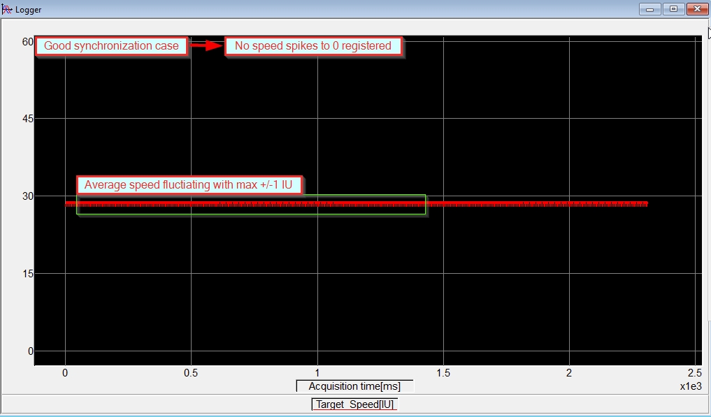
When the EtherCAT synchronization works correctly, the target speed does not have such spikes to 0.
In case of a synchronization issue, the debugging can be started with the steps below.
1. If an absolute encoder is used, check the drive fast loop sampling periods
The absolute feedback sensors (e.g. SSI, BiSS, EnDAT etc.) reading can be detrimental to the synchronization process. The drive may not be able to read the sensor and perform the control and the EtherCAT communication is the set time.
In this situation, an EtherCAT synchronization issue can be avoided by increasing the fast loop sampling period. This can be done by modifying the “fast loop sampling frequency divider” parameter in the “Advanced” window accessible from the “Drive Setup” dialogue in the Easy SetUp or EasyMotion Studio.
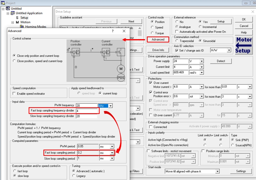
Remark: To apply the new values, downloaded the new setup to the drive and reset the drive.
2. Modify the “SYNC0 Offset” parameter on the EtherCAT master side
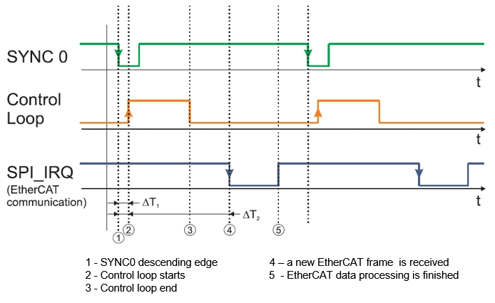
The “SYNC0 Offset” parameter defines the time difference between the “SYNC0” descending edge and the start of the EtherCAT Communication Loop (∆T2).
The “SYNC0 Offset” parameter should be available in the EtherCAT master configuration side. Below is an example from TwinCAT - Beckhoff’s EtherCAT master software interface).
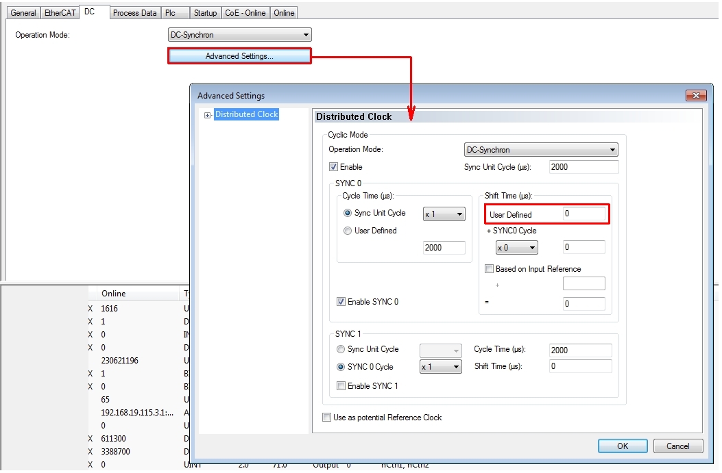
By default, the “SYNC0 Offset” parameter is 0. In case of a synchronization issue, it can be increased to 100 µs, 200 µs, 300 µs and so on (up to 900 µs) until the synchronization issue is solved.
If the EtherCAT master doesn’t have or if it doesn’t allow to change the “SYNC0 Offset” parameter value, the synchronization issue can be prevented by adding an offset between the synchronization signal (SYNC0) and the “Control Loop”. This offset value can be introduced through the object 2109h (sync offset) or through the “SLsyncOffset” TML parameter (the difference between the “SYNC0” signal start time and the “Control Loop” start time - ∆T1).
By default the offset value is 1000 but when a synchronization issue is detected, it can be set to 20000 or 25000.
To make sure that the offset value assures a good EtherCAT synchronization, an external oscilloscope can be used, to check the above signals and see if they meet the conditions listed in chapters “3.2.2 Synchronization signals” and “Object 2089h: Synchronization test config” from the “CoE Programming Manual”.
 Categories