In case of the DC brushed or brushless motors equipped only with an analog feedback sensor (e.g. potentiometer) the position or speed control is possible only with a special firmware, as follows:
- F6GEA firmware version for iPOS2401 MX-CAN, iPOS3602 VX/MX/BX/HX-CAN, iPOS3604 VX/MX/BX/HX-CAN and iPOS4808 VX-CAN;
- F6GYA firmware version for iPOS4808 MY/BX-CAN, iPOS8010 BX-CAN, iPOS8020 BX-CAN and iMOTIONCUBE.
The firmware versions mentioned above are not included in the standard EasyMotion Studio pack. To add them to the "Firmware" folder and install one of them (function on the used drive) to the board, the following steps must be done:
1) Check if EasyMotion Studio is up to date (Windows Start menu -> All programs -> EasyMotion Studio
-> Update via Internet);
2) Start EasyMotion Studio and restore the attached project archive (Project -> Restore);
3) Use the "Firmware Programmer" tool (included in the EasyMotion Studio software pack) to change the drive
firmware.
After the drive is programmed with the needed firmware, a new EasyMotion Studio project should be created, according to the used configuration.
Remarks:
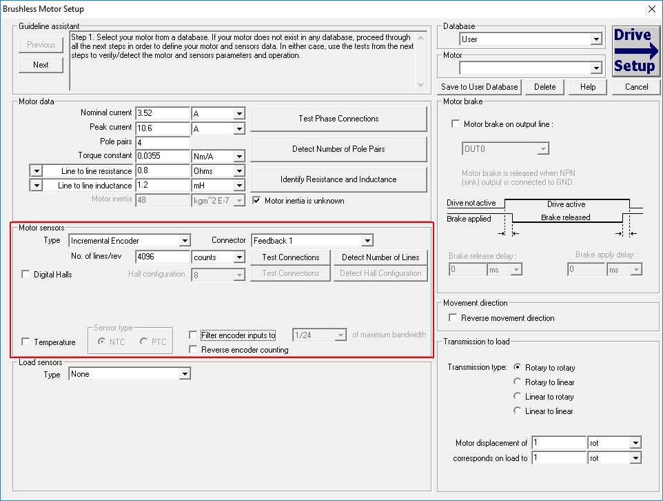
1) As the analog (potentiometer) feedback is not a standard option, a template for incremental encoder needs to be selected, when the new project is created;
2) The analogue (potentiometer) feedback sensor output will be connected to the drive "Feedback" (AD2) analog input. The connection diagram is presented in each drive user manual, under the "Analog Inputs Connection" chapter.
In the "Motor Setup" dialog, the "incremental encoder" option will be chose as "motor feedback". The encoder resolution will be set to 4096 counts (1024 lines). This value comes form the drive analog input resolution. The AD converter on the Feedback input has 12 bits, so 2^12=4096 values.
After the encoder resolution is set to 4096 counts and the required firmware is forced to the special one, the setup can be done as in case of any other project.
Working with an analog signal, some offsets and filters may be needed. These can be set and applied through a set of TML parameters, that are different, function on the used firmware.
F6GA firmware version
1) POS_FILTER - low pass first order filter
that can be applied to the analogue input.
- Default value: 32767 (filter deactivated);
- Valid values: 0 ... 32767, where 0 means... full filtering and 32767 means no filtering.
This
parameter can be modified using the "POS_FILTER, dm = filter_value;" TML instruction, that can be typed in the Command Interpreter dialogue or inserted in the "Motion" branch, at the TML program beginning.
2) APOSOFF - position offset
- Default value: 0;
- Valid values: -2048 ... 2047.
This parameter can be used to apply an offset to the
analogue input reading, before copying it into the actual
position (APOS) and can be modified using the "APOSOFF, dm = offset_value;"
TML instruction, that can be typed in the Command Interpreter dialogue
or inserted in the "Motion" branch, at the TML program beginning.
In this case, the actual position value will be computed as:
APOS = Analogue_input_reading [0…4095] –
APOSOFF
F6GYA firmware version
In this firmware case, the analogue sensor indication is read (by default) from the "Feedback" analogue input (AD2) but the "Reference" analogue input (AD5) can also be used for the sensor reading. The source of the analog signal is programmable through the "apos_from_anlg_selection" parameter (int@0xBA51). When this parameter is set to 0, the analog feedback is read through the "Feedback" analogue input (AD2). When it is set to 1, the analogue signal is read through the "Reference" analogue input (AD5).
Remark: The position value will be visible in the APOS_LD variable that in this case has the same value as the APOS values.
The analogue feedback filtering and offset can be done through the following parameters:
1) FILTER1 - low pass first order filter
that can be applied to the analogue input.
- Default value: 32767 (filter deactivated);
- Valid values: 0 ... 32767, where 0 means... full filtering and 32767 means no filtering.
This
parameter can be modified using the "FILTER1, dm = filter_value;"
TML instruction, that can be typed in the Command Interpreter dialogue
or inserted in the "Motion" branch, at the TML program beginning.
2) AD2OFF - position offset
- Default value: 0;
- Valid values: 0 ... 65535.
This
parameter can be modified using the "AD2OFF, dm = offset_value;"
TML instruction, that can be typed in the Command Interpreter dialogue
or inserted in the "Motion" branch, at the TML program beginning.
A shift can also be applied to the analog data, before even subtracting the offset. This can be done through the SHIFT_POS (int@0xBA45) paramter.
The actual position value will be computed as:
APOS_LD = Filtered ((AD2(5) >> SHIFT_POS) - AD2OFF)
 Categories
