As the iPOS drives are fully digital, a standard analog output is not available.
For such cases, in which an analog output is required, it can be emulated using one of the drive PWM outputs. The output voltage being controlled by modifying the PWM output duty cycle.
If the drive controls a step motor, this configuration is not possible, as all of the PWM outputs will be involved in controlling the motor.
If the drive controls a DC or a brushless motor then the 4th PWM output (the "break" pin) can be set to emulate the analog output.
The 4th PWM output can be set as "break" pin from the Drive Setup dialogue.
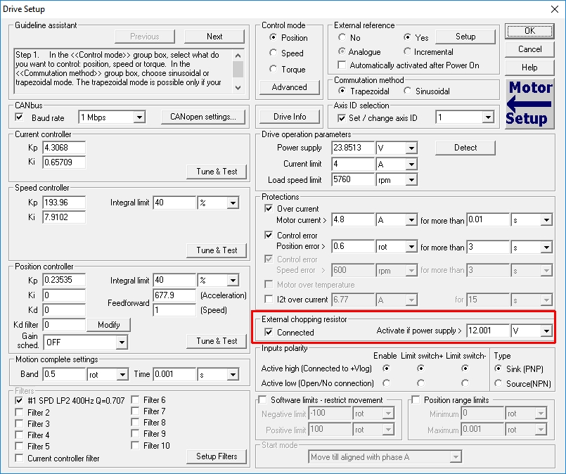
The value inside the "External chopping resistor" it's not so important because it will be set in the TML program.
The PWM output duty cycle on the "brake" pin can be changed by writing a value between 10 (~ 100% duty cycle) and 3000 (0% duty cycle) to the address 0x68C9. This can be done using the code below.
/* User variables definition */
int adr; // Define integer variable adr
/* Set the "adr" user variable with the address of the braking pin PWM duty cycle parameter (0x68C9) */
adr = 0x68C9;
/* Set the voltage level for the "external chopping resistor" pin activation (it should be lower than the drive supply voltage). */
BRAKELIM = 1000;
/* Change the value below from 10 to 3000, to select the desired duty cycle for the 4th PWM output (e.g. 10 - ~100% | 1500 - 50% | 3000 - 0%) */
(adr),dm = 3000; //Set data located in DATA memory at address contained in adr
The PWM frequency on the "brake" pin is 10 kHz
on the IPOS2401, iPOS3602 and iPOS3604 drives and 15 kHz on the iPOS4808, iPOS8010/8020 and iMOTIONCUBE drives.
Following the above code execution, the drive will pulse (on the "braking" pin) the "Vmot" voltage. As in most of the cases the analog output is required to pass an information to an external device, these pulses should be converted, for example, to a 0 V ... 5V signal. This can be done using the following circuit.
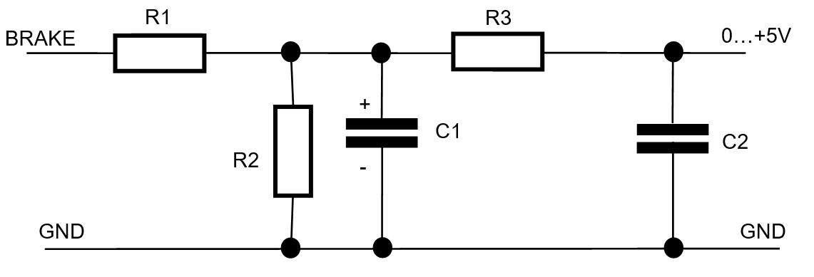
R1 = 820 Ohms; 1W;
R2 = 220 Ohms;
R3 = 1 kOhms;
C1 = 10 micro Farads
C2 = 1 micro Farad
Error = 6% (at 24 V)
Remark: The values above were computed for a supply voltage (on the "Vmot" line) of 24 V.
Using discrete components (hrough-hole), the schematic above has the advantage that it is simple. Unfortunately it has a disadvantage too. There's an error on the outputted voltage.
In case of a complex application where the analog signal accuracy matters, the above circuit should be replaced with a more complex one. Its schematic is attached at the end of this article ("PWM 2 Analog Conversion Circuit Schematic.pdf"). Thia schematic has the advantage that works with an input voltage ("Vmot") from 12 V to 80 V and can output an analog signal of 0V ... 5V or 0V ... 10V (this can be selected through a micro-switch or jumper).
For a better understanding, a demo project was attached to this article. It contains a TML application that reads the load speed (ASPD) and compute the "brake" pin duty cycle so a 0V ... 5V analogue signal will be obtained the output of the above circuits.
To restore the project archive below, download it to the PC and follow the instructions in the following article:
- http://www.technosoft.ro/KB/index.php?/article/AA-00292
 Categories

